X-RAY DIAGNOSTIC IMAGING
Learning Objectives
- Production of x-rays
- Forming x-ray images
- Advanced imaging techniques
- Digital imaging
X-RAY TUBE
The Basics
A basic x-ray tube is formed of a cathode filament, an anode metal target enclosed in an evacuated glass bowl. There is also a shield which encloses this again, with only a small window to allow x-rays to pass through.

Current is applied through the filament, and there is thermionic emission of electrons from the filament. Then a high voltage is applied across that, causing electrons to flow across to the target leading to the emission of x-rays.
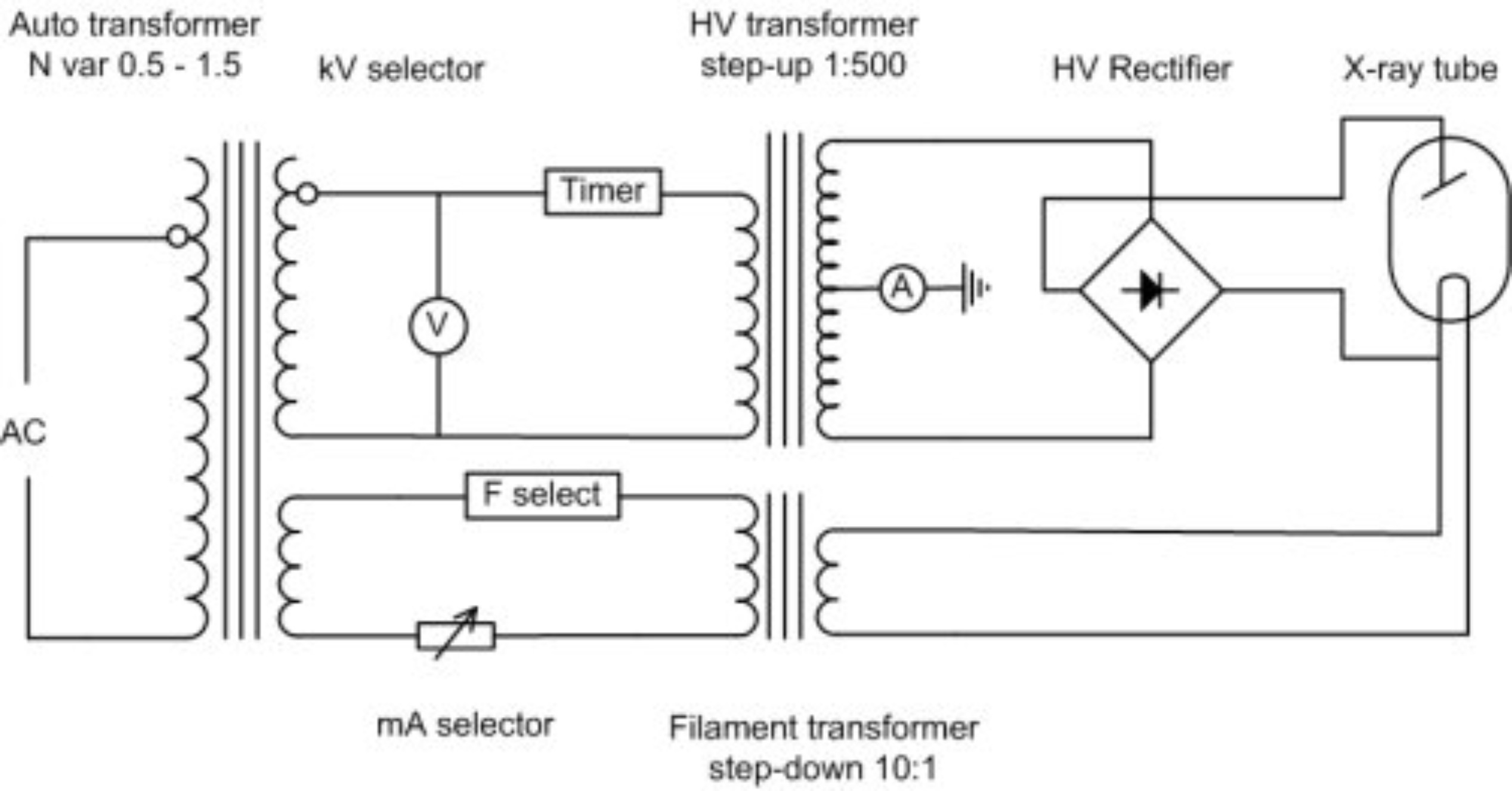
kV Control Circuit
The HV Rectifier ensures that there is always a positive voltage on the anode relative to the cathode. So in essence a sine wave is always positive (negative values are reflected back to positive values along x-axis), this is also called a full wave rectifier. In a half wave rectifier only the positive or negative values are rectified not both.
Modern X-Ray tubes
In modern x-ray tubes the anode rotates to prevent overheating as almost 99% of the energy required to produce x-rays is converted to heat. It is a very inefficient process. The whirring sound which you hear when having an x-ray is causing by the rotating anode, and the ‘clunk’ is the x-ray itself, the high voltage part of it. The cathode has one or more filaments (often two) to give a broad focus and a fine focus. This helps with the resolution of the x-ray tube.
If you overheat an anode, it can become significantly damaged, with concentric circles becoming apparent where the electrons are focused. And if the anode stops spinning but electrons are still ‘fired’ at it pitting can occur as well, effectively destroying the tube.
The tube housing encases the the x-ray tube. It is often made out of lead and it stops x-rays from being scattered in every direction. It contains a window from which they are emitted with a filter (often aluminium) blocking the lower energy x-rays as these do not help to form an image. Therefore reducing the amount of radiation the patient is exposed to.
Note: Photon energy is measured in kVp
Below the housing is a light-beam diaphragm which is co-incident with the x-ray beam. This shows the radiographer where the x-ray images be taken of the patient.
X-Ray Spectrum
The x-ray spectrum is formed from Bremsstrahlung (a continuous element) and a series of characteristic x-rays.

Note: In a diagnostic x-ray machine Bremsstrahlung is most important, radiographers are not really interested in the characteristic x-rays
1. Bremsstrahlung Radiation
Is the electromagnetic radiation produced by the deceleration of a charged particle after passing through the electric and magnetic fields of a nucleus. The kinetic energy that is lost by the charged particle is emitted as an electron.
2. Characteristic X-rays
Characteristic X-rays are produced when a material is bombarded with high-energy particles (electrons), some of the electrons surrounding the atom are ejected. These spaces created around the atom need to be filled. These outer electrons in higher shells cascade down to fill the vacancies causing emission of x-rays of characteristic of element.
For example, as electrons travel from the L shell to the K shell, creates a K-alpha x-ray. If an electron falls from the M to the K shell a K-beta x-ray is emitted.
Note: Innermost shell is K then L and Outermost shell is M
Tissue Attenuation
To form images, x-rays must attenuate in tissue. There are two iterations that happen at diagnostic energies, the Photoelectric effect and the Compton effect.
1. Photoelectric Effect Inner shell Z Dependent
The photoelectric effect is a form of interaction of X-ray or gamma photon with the matter. A low energy electron interacts with an electron in the atom and removes it from its shell. This is very likely if the electron is:
- Tightly bound (as in k shell)
- The energy of the incident photon is equal to or just greater than the binding energy of the electron in its shell
The electron that is removed is called a photoelectron; the incident photon is completely absorbed in the process; all photon energy is transferred to the electron.
Electron energy = Photon energy - Binding energy of electron
The photoelectric effect is related to:
- the atomic number (Z) of the attenuating medium
- the energy of the incident photon
- the physical density of the attenuating medium
Small changes in Z can have quite profound effects on the photoelectric effect, this has practical applications in the field of radiation protection. Hence materials with a high Z, e.g. lead (Z = 82) are useful shielding materials.
2. Compton Scatter Outer shell Z Independent
Compton scatter is one of the main causes of scattered radiation in a material. It occurs due to the interaction of the X-Ray or gamma photon with free electrons/loosely bound valence (outer) shell electrons. The resultant incident photon gets scattered (changes direction) and transfers energy to the recoil electron. The scattered photon will have a different wavelength and thus a different energy. The Klein-Nishina formula describes the compton effect and shows how energy and momentum are conserved.
The scattered x-rays therefore have a longer wavelength (and a lower energy) than those incident on the material. The Compton effect does NOT depend on the atomic number (Z) of the material, but does depend strongly on electron density.
Diagnostic Range Attenuation 30 - 120 Kev
The standard x-ray is a negative image with the bones in white representing a higher attenuation. Bone is significantly more attenuated at lower energies than the soft tissues (muscles and fat) which are represented by a grey colour. No attenuation leads to a black image, for example in the lungs or the gut (because they are full of air). This difference in attenuation gives the x-ray image. Radiating at a lower energy reduces photon attenuation and increases contrast.
Attenuation formula
$ n_x = n_0 e^{-\mu x} $
μ is the attenuation coefficient
Producing Images with X-rays
There are two properties that are most talked about which are contrast and sharpness (resolution).
1. Contrast
A ‘flat image’ is an image with little contrast and is often due to a high amount of attenuation. Radiating at lower kVs reduces attenuation (using photoelectric effect) and leads to higher contrast in the image.
2. Sharpness
This is partly a property of an X-ray tube. A larger filament leads to a worse image resolution, and bad image resolution often has a large penumbra (a region of ‘partial eclipse’ or geometric ‘unsharpness’). Also if the imaging plate is not directly beneath the object the penumbra increases. Inside the cathode, a large wire filament can be used within the focusing cup to produce a large focal spot; a small filament can be used for a small focal spot. However, there is a disadvantage to having a small penumbra (and high resolution image): electrons are concentrated on a small area, which is more damaging to the X-ray tube.
Scatter Problem
Scatter due to the Compton effect does not help image formation and adds a ‘fog’ to the image. You can prevent excessive scatter noise by using an anti-scatter grid, although this means there is a higher dose given to the patient; with an anti-scatter grid you need more X-rays to form a good image.
Contrast Agents
Contrast agents are used to improve images produced by X-ray, CT, MRI and ultrasound. These substances temporarily change the way x-rays or other tools interact with the body. When introduced to the body, contrast materials help to distinguish certain structures/tissues to allow diagnosis of medical conditions.
- Barium: has a very high Z value and is the most common contrast agent taken orally and rectally (barium enema). It is available in several forms including powder, liquid and tablet.
- Iodine is often used when we need a contrast agent in the blood, e.g. to monitor filtration of the agent out of the blood by the kidneys.
- Barium and air: in a double contrast study, the colon is first filled with barium, then drained so that only a thin layer of barium is left on the wall of the colon. When the colon is filled with air, this provides an extremely detailed view of the inner surface of the colon.
Moving Images Image intensifier
An image intensifier has a large area at the front and a small area at the back to minify the image and accelerate electrons to give you the energy enhancement sufficient to produce a good image on a screen. Examples of use include conventional fluoroscopy and a C-Arm image intensifier used in a cardiac/angiography room to look at problems in the heart.
How does it work?
The x-rays interact in a photocathode (caesium iodide) which changes them to electrons. The electrons are then accelerated across a voltage and are focused on output screen (phosphor).

An example of the use of an image intensifier is in combination with iodine contrast media to look at a beating heart, watching for any irregularities. Another use is in combination with barium and looking at swallowing in the oesophagus.
X-Ray Detector Technologies
Advances in technology has allowed us to move on from viewing X-ray on an analogue screen/film to digital ways of looking at X-Ray images. An old digital process was the use of Computed Radiography (CR) with imaging plates. However hospitals these days use Direct Digital Radiography (DDR) which is an instantaneous process as the imaging plates are now made up of diodes. With this process there is no need to wait for film to be developed or read CR plates.
Digital Processing
Digital images allow radiographers to enhance them by zooming, inverting, post processing, filter and edge enhancing. These allows them to manipulate the images allow them to see certain structures such as blood vessels more easily.
Digital Subtraction involves taking two images, one before contrast injection and one after. If you subtract one from the other you end up enhancing the structure you want to see more clearly. However a drawback is that there can’t be any movement between the two images.
Dual Energy X-Ray Absorptiometry DEXA
Dual-energy X-ray absorptiometry is a means of measuring bone mineral density (BMD). Two X-ray beams irradiate at different energy levels and are aimed at the patient’s bones. When soft tissue absorption is subtracted out, the BMD can be determined from the absorption of each beam by bone. Dual-energy X-ray absorptiometry is the most widely used and most thoroughly studied bone density measurement technology. It is a very low dose technique commonly used for people with osteoporosis.
Written by Tobias Whetton