Alternating current
Introduction
Until the late 19th century, direct current was exclusively used. George Westinghouse then introduced alternating current which was far from being widely accepted at the beginning. He was arguing that using high voltage alternating current instead could carry electricity much further than direct current with marginal loss of power. After several years of fight against Thomas Eddison - defender of direct current- Westinghouse finally won the “war of currents” and alternating current was introduced. This lecture, as well as the following three, will investigate several methods and tools useful for alternating current analysis.
Learning objectives
- Alternating current (AC) and voltage
- AC waveforms
- Phasors
- Inductive/capacitive reactance
- AC series circuit
- Resonance series circuit
Waveforms and phasors
Direct current is defined as a current where the potential difference is independent of time; alternating current’s voltage depends on time.
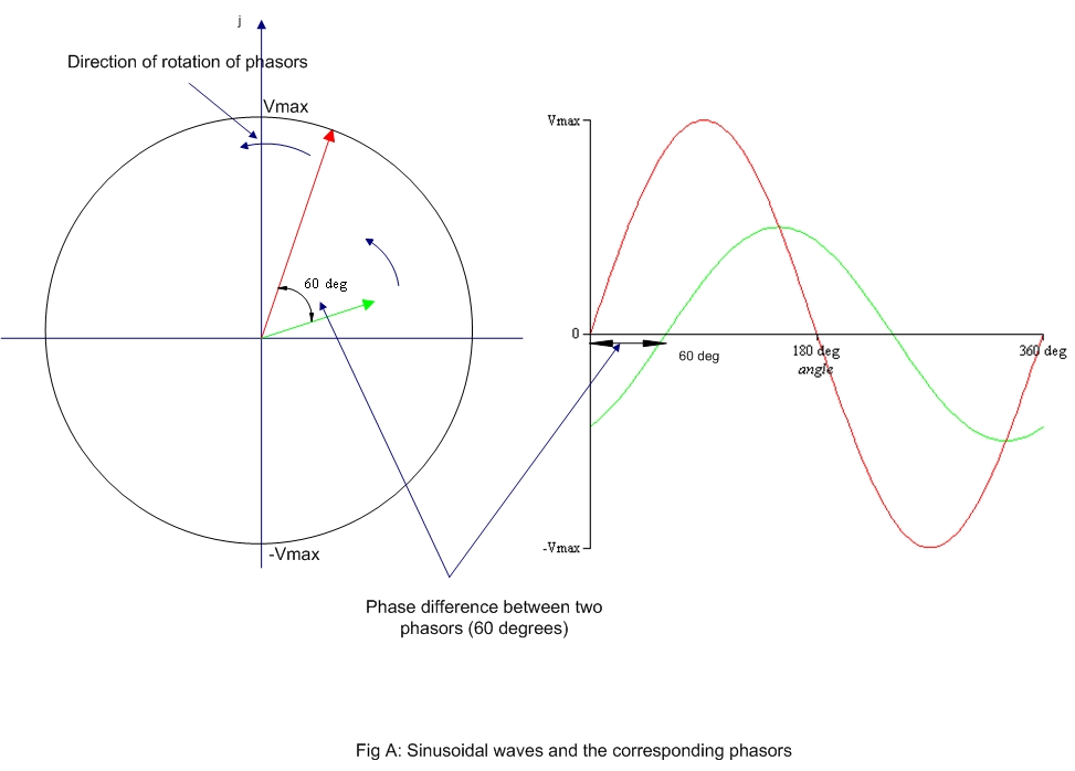
When plotting the current produced by an alternating current source against time, a sinusoidal wave appears. As a regular wave, this one can as well be defined by its amplitude A, period T, frequency F and phase angle $ \theta $. Analysis of alternating current is hence done using all these wave characteristics. However, geometrical study of waves can sometimes get laborious, some tool are hence used to make the analysis easier. One of these tools is the phasor.
A phasor is a geometrical entity that helps us to describe and analyse physical quantities that vary sinusoidally with time just like alternating current. Obviously, basic algebra can be done with phasors.
AC circuit analysis
Introduced in lecture 4, inductance and capacitance are widely used with alternating current and in our every day life. Both these tools, as well as the resistor, have specific impacts on the AC circuit.
Purely resistive AC circuit
As the name clearly states it, a purely resistive AC circuit is a circuit which only contains a resistor and a power source (hence no inductor or capacitor). Ohm’s law defined in lecture 1 is applicable in a very similar way as in DC circuit in this case, except that time is now something to take into account:
Purely Inductive AC circuit
In a purely inductive AC circuit, the relationship between current $i_L$ and voltage $v_L$, is given by Faraday’s law. Also, a new concept is introduced: the inductive reactance $X_L$, defined as $ \omega \times L $. The unit of inductive reactance is the Ohm
Purely capacitive AC circuit
In a purely capacitive AC circuit, the relationship between current $i_C$ and voltage $v_C$ also requires a new concept: the capacitive reactance X_C, defined as $\frac {1}{\omega \times C }$. The unit of capacitive reactance is the Ohm
CIVIL
In a capacitor
| Element | Amplitude relationship | circuit quantity | Phase of $\nu$ |
|---|---|---|---|
| Resistor | $ v(t)=i(t) \times R$ | R | In phase with i |
| Inductor | $ V_L=X_L $ | $X_L=$ \omega \times L $ | Leads i by 90degrees |
| Capacitor | $V_C=X_C I$ | $X_C= \frac {1}{\omega \times C }$ | Lags i by 90 degrees |
R-L AC circuit
Circuit containing a resistor and inductor (no capacitor) I lags the applied voltage in this circuit by an angle $\phi$ lying between 0 and 90 degrees. Also, a new concept is here introduced: in AC circuit, the ratio $\frac{V}{I}$ is called the impedance Z. Its amplitude and phase are given as follows:
R-C AC circuit
Circuit containing resistor and capacitor (no inductor). I leads the applied voltage V by an angle $\alpha$ between 0 and 90 degrees. The concept of impedance is the same here, except that inductive capacitance is replace with capacitive reactance.
R-L-C AC circuit
Circuit containing a resistor, a capacitor and an inductor.
The applied voltage is the phasor sum of V_R, V_L and V_C. V_Cand V_L are anti-phase (i.e. displace by 180 degrees).
Three different cases possible:
«««< HEAD
-
$X_L > X_C : $
-
$X_L > X_C$ »»»> 909c1836775a43123028537885ce20ffccba239f
-
$X_L < X_C :$ $
-
$X_L = X_C :$ The applied voltage V and the current I are in phase, this effect is called series resonance. In this case:
The series resonant circuit is often described as an acceptor circuit since it has its minimum impedence, and thus, maximum current, at the resonant frequency. Since $X_L= X_C$. we have: . , The resonant frequency is given by :
Written by Yassine Benchekroun