Electrical circuits are everywhere. Learn the basics of alternating and direct circuits and the laws associated with them. The current chapters are:
Learning objectives of the lecture
- Electrostatic fields strength, Electric flux density
- Capacitance
- Capacitors in parallel and series
- Energy
- Magnetic flux and flux density, permeability
- Inductance
- Inductors in series and parallel
A capacitor is an electrical device that is used to store electrical energy. Next to the resistor the capacitor is most commonly encountered component in encountered component in electrical circuits. They are used in time delay circuits and in in time delay circuits and in electrical filters and oscillators. The latter are also used in Magnetic Resonance Imaging (MRI) for transmitting and receiving radiofrequency signals.
Given by Coulomb’s law, the force of attraction or repulsion between two electrically charged bodies at distance d is given as follows :
Capacitance is the ability of a body to store electrical charge. The capacitance C is given by the following equation $ C=\frac{Q}{V} $
The SI units for capacitance is farads (F) or Coulomb per Volt as suggests the formula. Note that the charge Q is current times time (Q= I⋅t)
The electric flux $ \psi $ is proportional to the number of electric field lines going through a virtual surface. It is measured in Coulombs
For a charge of Q Coulombs, the flux is \psi = Q Coulombs. Now, the electric flux density is the amount of flux passing through an area A that is perpendicular to the direction of the flux. $ D=\frac{Q}{A} $ measured in C.m-2
It is the measure of resistance that is encountered when forming and electric field in a medium:
$ \varepsilon_0 $ is the permittivity of free space. When an insulating material (dielectric) such as paper, mica or ceramic is introduced into the electric field, the ratio is modified:
$ \frac{D}{E}=\varepsilon_0 \varepsilon_r $; where $ \varepsilon_r $ is the relative permittivity
It has no units and some typical values are listed below:
It is simply proportional to the area A of a plate and inversly proportional to the plates’ spacing d. Also depends on the dielectrics between the plates: n being the number of plates (a capacitor is at least made of 2 plates of course)
What needs to be remembered is that capacitors in parallel acts exactly like resistors in series: they just add up. Hence if the circuit for example has only three capacitors in parallel, the total capacitance is given as follow :
This of course works the opposite way : exactly like resistors in series. Hence if the circuit has for example three resistors is series, the total resistance is given as follow :
The energy stored by a capacitor is given by :
Chapter to be completed…
Until the late 19th century, direct current was exclusively used. George Westinghouse then introduced alternating current which was far from being widely accepted at the beginning. He was arguing that using high voltage alternating current instead could carry electricity much further than direct current with marginal loss of power. After several years of fight against Thomas Eddison - defender of direct current- Westinghouse finally won the “war of currents” and alternating current was introduced. This lecture, as well as the following three, will investigate several methods and tools useful for alternating current analysis.
Learning objectives
- Alternating current (AC) and voltage
- AC waveforms
- Phasors
- Inductive/capacitive reactance
- AC series circuit
- Resonance series circuit
Direct current is defined as a current where the potential difference is independent of time; alternating current’s voltage depends on time.
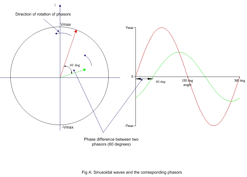
When plotting the current produced by an alternating current source against time, a sinusoidal wave appears. As a regular wave, this one can as well be defined by its amplitude A, period T, frequency F and phase angle $ \theta $. Analysis of alternating current is hence done using all these wave characteristics. However, geometrical study of waves can sometimes get laborious, some tool are hence used to make the analysis easier. One of these tools is the phasor.
A phasor is a geometrical entity that helps us to describe and analyse physical quantities that vary sinusoidally with time just like alternating current. Obviously, basic algebra can be done with phasors.
Introduced in lecture 4, inductance and capacitance are widely used with alternating current and in our every day life. Both these tools, as well as the resistor, have specific impacts on the AC circuit.
As the name clearly states it, a purely resistive AC circuit is a circuit which only contains a resistor and a power source (hence no inductor or capacitor). Ohm’s law defined in lecture 1 is applicable in a very similar way as in DC circuit in this case, except that time is now something to take into account:
In a purely inductive AC circuit, the relationship between current $i_L$ and voltage $v_L$, is given by Faraday’s law. Also, a new concept is introduced: the inductive reactance $X_L$, defined as $ \omega \times L $. The unit of inductive reactance is the Ohm
In a purely capacitive AC circuit, the relationship between current $i_C$ and voltage $v_C$ also requires a new concept: the capacitive reactance X_C, defined as $\frac {1}{\omega \times C }$. The unit of capacitive reactance is the Ohm
In a capacitor
| Element | Amplitude relationship | circuit quantity | Phase of $\nu$ |
|---|---|---|---|
| Resistor | $ v(t)=i(t) \times R$ | R | In phase with i |
| Inductor | $ V_L=X_L $ | $X_L=$ \omega \times L $ | Leads i by 90degrees |
| Capacitor | $V_C=X_C I$ | $X_C= \frac {1}{\omega \times C }$ | Lags i by 90 degrees |
Circuit containing a resistor and inductor (no capacitor) I lags the applied voltage in this circuit by an angle $\phi$ lying between 0 and 90 degrees. Also, a new concept is here introduced: in AC circuit, the ratio $\frac{V}{I}$ is called the impedance Z. Its amplitude and phase are given as follows:
Circuit containing resistor and capacitor (no inductor). I leads the applied voltage V by an angle $\alpha$ between 0 and 90 degrees. The concept of impedance is the same here, except that inductive capacitance is replace with capacitive reactance.
Circuit containing a resistor, a capacitor and an inductor.
The applied voltage is the phasor sum of V_R, V_L and V_C. V_Cand V_L are anti-phase (i.e. displace by 180 degrees).
Three different cases possible:
«««< HEAD
$X_L > X_C$ »»»> 909c1836775a43123028537885ce20ffccba239f
$X_L < X_C :$ $
$X_L = X_C :$ The applied voltage V and the current I are in phase, this effect is called series resonance. In this case:
The series resonant circuit is often described as an acceptor circuit since it has its minimum impedence, and thus, maximum current, at the resonant frequency. Since $X_L= X_C$. we have: . , The resonant frequency is given by :
«««< HEAD
#### Learning objectives of the lecture
======= > # Learning objectives > >* DC transients >* Current growth and decay in LR and RC circuits >* Integrator and Differentiator circuits
909c1836775a43123028537885ce20ffccba239f If a D.C. voltage source is connected in series to a circuit with inductance L and resistance R, there is a short period of time immediately after the voltage is connected during which the current flowing in the circuit and the voltages across L and R are changing. The same occurs when a capacitor C and resistor R are connected in series. These changes in voltage are calles transient . Note: The proofs for the following equations may (probably will) be asked for during the exam. The lecture notes on Keats clearly show every steps to follow.
Three different equations are to be remembered concerning the current growth in a circuit with inductance and resistance in series. For a LR circuit, $\tau$ is defined as follows: $\tau=\frac{L}{R}$
Similarly to the current grow, three equations need to be remembered For a LR circuit, $\tau$ is defined as follows: $\tau=\frac{L}{R}$
Four equations need to be remembered when it comes to charging a capacitor. In an RC circuit, $\tau$ is defined as follows : $\tau= RC$
Similarly to the charge of a capacitor, four equations need to be remembered In an RC circuit, $\tau\ $ is defined as follows : $\tau$= RC
Learning objectives
- AC parallel circuit
- Solving AC circuits using complex numbers
- Resonance Parallel circuit
- Rectification and smoothing of AC
As shown in in previous chapters, several types of circuits in AC can be built, which will be analysed differently. Using phasor diagrams can become very complicated with parrallel networks containing more than two branches, in these cases, using complex numbers may be appreciated
$Z=\frac{V_R\angle 0^o}{I_R\angle 0^o}$
$Z=\frac{V_L\angle 90^o}{I_L\angle 0^o}=X_L\angle 90^o =\jmath X_L$
$Z=\frac{V_C\angle -90^o}{I_C\angle 0^o}=X_C\angle -90^o =-\jmath X_C$
The RLC circuit has total impedance : $Z=R+ \jmath(X_L-X_C)$ If$ (X_L=X_C)$, by the equation above, minimal impedance Z is obtained with Z=R. It is said that the circuit is at resonnance
In AC circuit containing several impedances connected in series (Z1, Z2…), the total equivalent impedance ZT is given by: ZT=Z1+ Z2…
It is in Parallel AC circuits that the power of complex numbers can fully be apprecited. Some key concepts need to be defined before starting to solve AC parallel circuits.
It is the reciprocal of impedance Z $Y=\frac{I}{V}$ Unit: Siemen As Impedance is defined with a real and imaginary part (Z=R+jX), Admittance can be similarly defined as Y=G+jB with G as conductance and B as susceptance.
This is very similar to direct current, except that resistance is replaced with impedance Z. As with resistance, the total impedance of a circuit containing an impedance in each branch add up as follows: $\frac{1}{Z_T}=\frac{1}{Z_1} + \frac{1}{Z_2} …$ The problems with AC circuit are now easily solved with complex form, exactly as if solving a parallel circuit with DC (same current divider equations applicable, with impedance instead of resistance).
The total admittance of an L-R-C parallel circuit is given by The circuit is at resonance when the imaginary part is zero, in other words: $\omega C= \frac{1}{\omega L}$. This result in minial admittace $Y_r=\frac{1}{R}$
A more practical network contains a coil of inductance L with resistance R in parallel with a pure capacitance C. The following equation is thus obtained: $ Y= \frac{R}{R^2 + (\omega L)^2}+\jmath(\omega C -\frac{\omega L}{R^2 +(\omega L)^2}) $
Since at resonance, the imaginary part is zero, omega is thus written as follows: $\omega_R = \sqrt{\frac{1}{LC}-\frac{R^2}{L}}$
The rectification process is a process of obtaining unidirectional currents and voltage from alternating currents and voltages. Automatic switching in circuits is achieved using diodes. A diode is a two terminal electronic component with an asymmetric transfer characteristic with:
There are two main rectifications circuits: half wave and full wave circuits.
Smoothing is the process of removing the worst of the output waveform variations. To smooth out the pulsations a large capacitor C, is connected across the output of the rectifier, the effect is to maintain the output voltage at a level which is very near to the peak of the output waveform.